Hokay, so I will try and answer some of the FAQ about wiring in this thread. I'm going to start very basic and eventually work into some of the more complicated aspects to wiring. I know that for most people electrical is one of the most unattractive and intimidating things to and causes some people to shy away from it. My best advise: Dive in and just go for it.
One of the big things is to get basic tools need for wiring. Although things like diagonal cutting pliers work for stripping wires in a pinch, everything will be a lot easier if you go out and buy a halfway decent pair of wire strippers. Below I have a basic (left side) and a more complex (right side) "tool box" for wiring. Almost any wiring jobs can be done with a basic set.
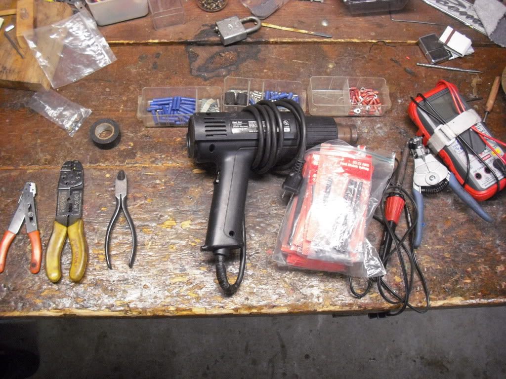
Basic tools:
-Wire cutters
-Wire Strippers
-Crimpers
-Electrical Tape
-Butt connectors & various wire connectors
Complex Tools (all of the above plus..)
-Auto strippers
-Shrink wrap
-Soldering Iron, gun, and solder
-Heat gun for shrink wrap
-Multi-meter. While not essential for wiring, it is very essential for troubleshooting.
The very basics:
Before you do any wiring on your vehicle, you should disconnect the battery. While 12 volts wont kill you, it can give you a good jolt, make unexpected sparks if you touch a live wire and a ground wire, and prevents things like relays from cycling as you connect or disconnect wires.
Whenever you disconnect a battery ALWAYS disconnect the negative (black lead) first, then the positive. When connecting a battery, always connect the positive lead (red) first. An easy way to remember this is: "Negative people leave first and arrive late" Cheesy, but hey it works.
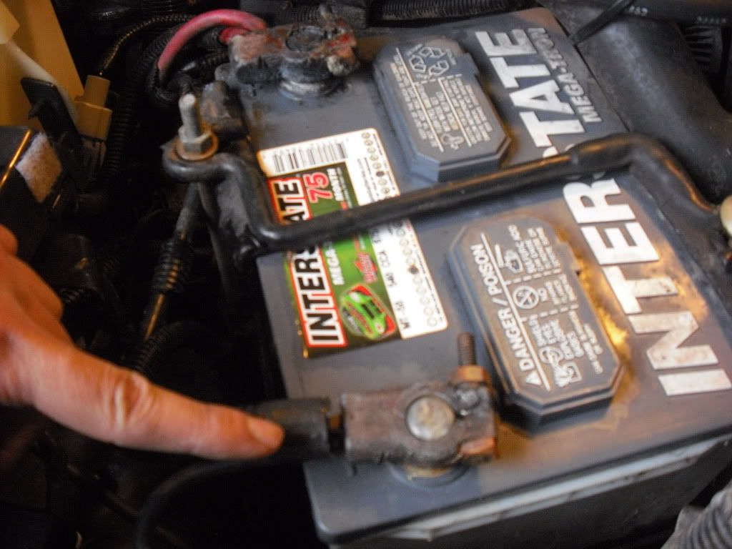
Negative lead
So you're ready to start throwing wires around:
I always found it best to lay everything out in front of you on a clean work area. Run out wires, separate connectors and splices, basically look at what you have before you get into it. Usually, I open the instructions to the wiring diagram but If you aren't good at reading them, the actual verbal directions usually aren't too bad either.
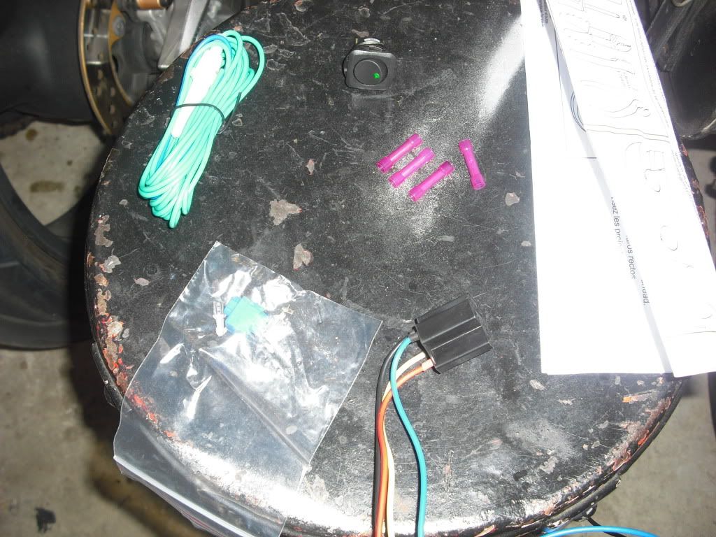
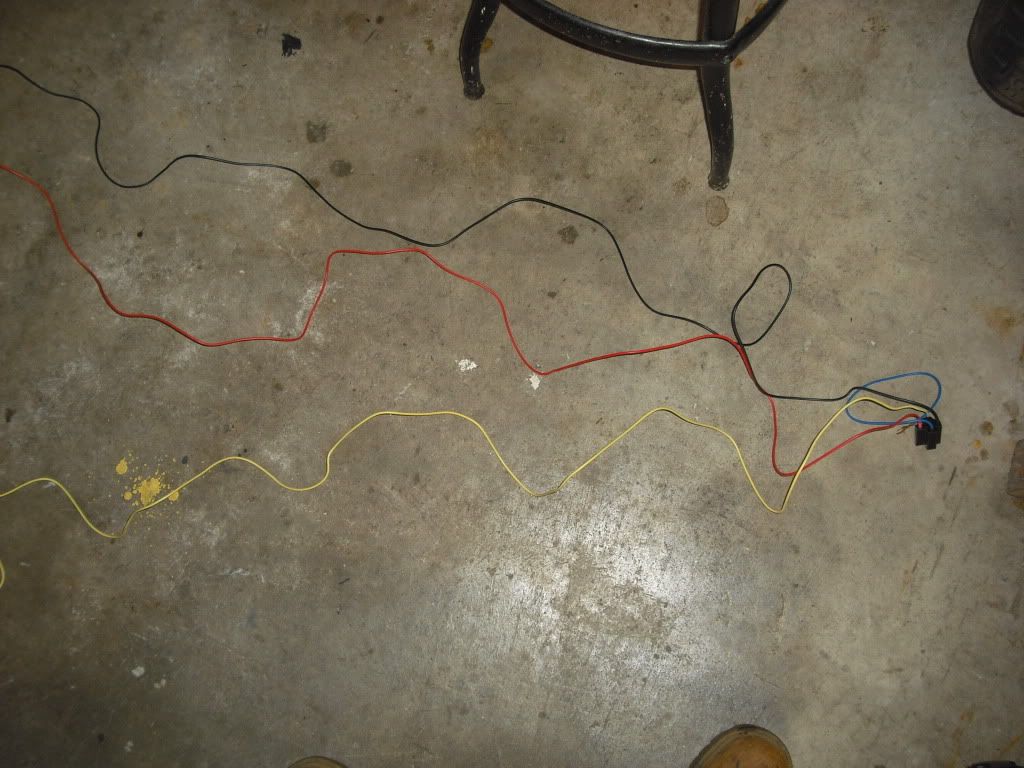
Doing this makes it a lot cleaner to wire things up. Only four wires here, doesn't look too bad now compared to that jumbled mess they gave you in the box right?
Ok, cool so now where the hell do I start?!
Personally, I always start on the switch and work from there. Pick where you want the switch, not where it will be the easiest to wire up. You'll be a lot happier in the long run. Work from the switch, to the component you're wiring, then to the battery. This way, when you get to the battery, connect everything up at once and you're all set.
GET ORGANIZED
I usually like to keep all my relays and fuses together. This way, when something goes wrong, you aren't fumbling around looking for where you put the relay or that fuse. If its all together and neatly bundled up, this makes troubleshooting go a lot smoother.
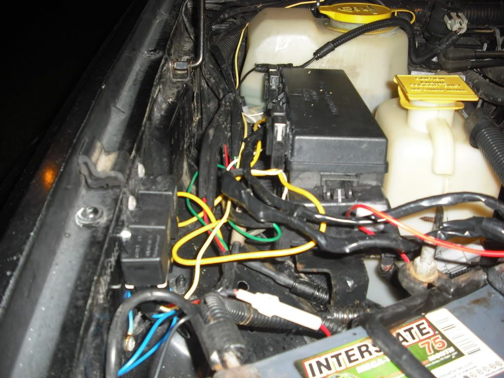
Relays on the fender and fuses on the fuse box. Doesn't get much easier then that.
Choosing a good ground
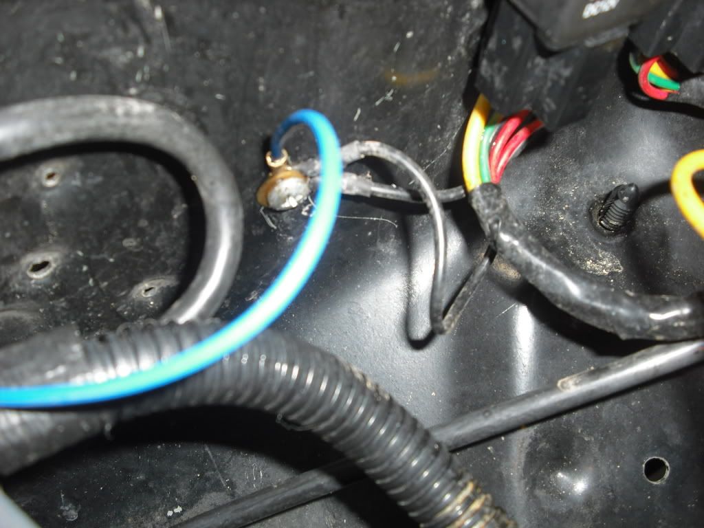
A good ground can make or break your project. Make sure your ground is a good metal to metal contact. This doesn't mean you need to sand the paint off the area you are going to use as a ground. A simple sheet metal screw through a wire lug (or eye) will provide a good ground as shown below.
Making the connections
Stripping
I would like to begin by saying that there is no need to strip back more then 1/4" - 1/2" MAX of insulation from basically any automotive wiring job with the exception of maybe battery terminals. Anymore and you're just exposing an unnecessary amount of wire to the elements. Remember that insulation also keeps wire temps down. The higher the temperature a wire gets, the higher the resistance.
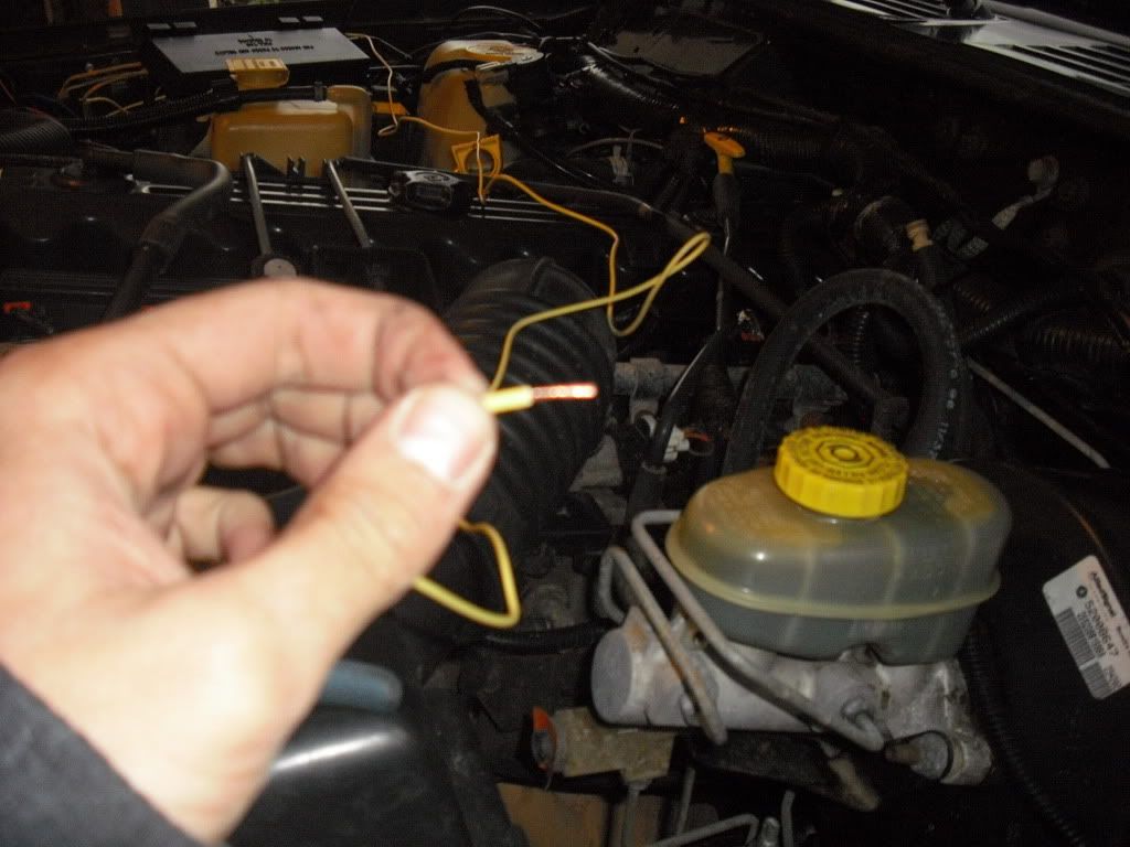
All you need to strip
Butt Splices
Later on, I'll post what color butt splice to use on what color wire. Generally, any 16gage wire will be red splice but you can get away with using a blue one too. Use the wire crimpers to crimp just off center of the splice. If your cripers have an insulation crimp (labeled INS. on the crimpers) then crip just at the beginning of the insulation. This helps make the splice water resistant but isn't waterproof.
Solder and shrink wrap
Honestly the best and strongest way to wire things but also the most time consuming and could be a PITA in tight areas. Always put the shrink wrap on first and size it up so its about 1/8" past the exposed wire and rated for that gauge wire, just use your judgment here. When soldering, twist the two wires you want to connect together but keep them in line with each other. What I mean here is keep it linear, don't make the twist perpendicular to the wires in a "T" shape. I like to start by putting a small bubble of hot solder on the tip of the iron and then touching it to the wire, as the wire heats up, it will suck in the solder bubble. Now just fill it in a little bit and you're good to go. Give it a little tug once it cools just to make sure its secure. Slide the shrink wrap over the connection and heat it with a heat gun (or your sisters hair drier, just wipe the grease off before you return it or she won't be too happy) to shrink the tube. Now that's a good WATER PROOF connection right there!
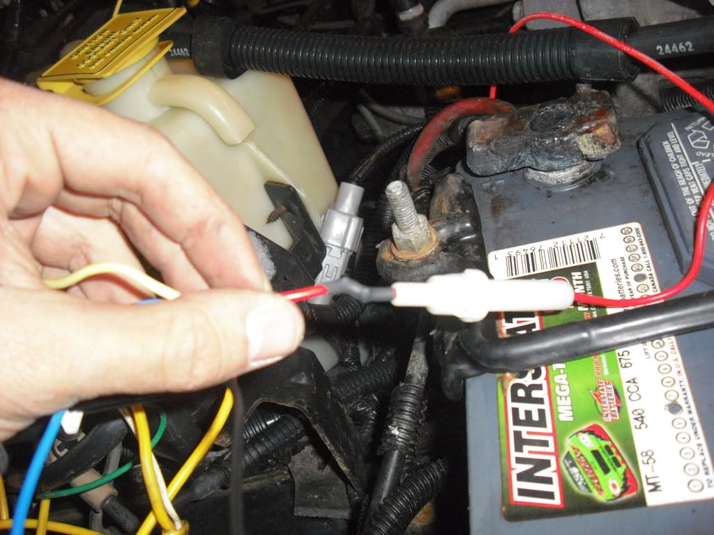
Solder and shrink tube with an inline tube style fuse.
RELAYS
Why should I use a relay?
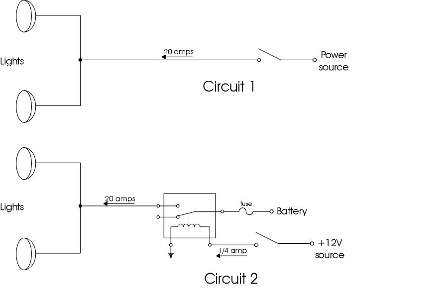
Continuing the example of wiring up lights which use high currents, the same current that goes to the light will go through the switch if you chose not to use a relay. Unless you buy a very heavy duty switch (the switch in many light packages is not heavy duty by any means) the switch will eventually fail.
Also, due to various losses and line resistance, there will actually be a measurable voltage drop by the time the current reaches the lights.
I should also mention that if you plan on hooking up a circuit by tapping into the fuse panel you can overload the factory circuit. The best case scenario is that it blows a fuse but you also run the risk of melting a wire or cause damage to whatever circuit you're hooked into.
How They Actually Work (The magic inside that little black box)
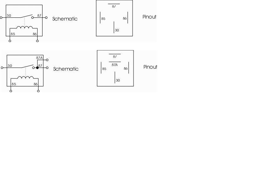
When +12V is applied between pins 85 and 86 the coil becomes a magnet which pulls the lever down making a connection between pins 30 and 87. Essentially, a relay is a magnetic switch
The picture below is drawn up to tie all of this together. If the relay was not used, a full line current of 20amps would be going through the switch. In this case, only a 1/4 amp is going through the switch. What would you rather have?
Wire Choices
A common question when choosing what wire to use when making a homemade circuit deals with the wires gauge. Before I talk about this though, I'm going to go over a few things about wire.
All wires carry a certain resistance within them. With that said, the resistance to flow creates heat (when you turn on a hair drier you can see the glowing heat coils inside; hair driers generally have high resistance. If you try this don't stick your face in front of it) The more power (watts) (side note- VOLTAGE IS NOT A UNIT OF POWER) you put through a wire the hotter it will get. As a wire gets hot, the resistance increases and, in extreme cases, can melt the insulation. If a wire with no insulation touches metal framework, now you have a ground. Worst case scenario, this could result in a fire. Ground detection will be discussed later in this thread.
In some respects, the capacity of a wire is actually best measured in watts, not amperage. This is mainly because the watt is a combination of amperage, voltage, and resistance. However, most wire charts are done in amps. For automotive wiring, this is perfectly fine. Anyway, below is a chart of MAX amperage for a given wire gauge:
GAGE AMPS (12VDC)
22 5A
20 8A
18 10A
16 20A
14 40A
12 60A
10 100A
8 150A
6 ??A
4 ??A
2 ??A
1 ??A
0 ??A
The Basic Basics of Troubleshooting
So lets say you wired something up, flipped that switch, and...nothing. Dammit, now what?
This is why most people HATE dealing with wiring and its definitely not the most fun part of owning a Jeep, but hey, lets face it, those sweet LED brake lights have to work right? ::coughcoughwillgentilecoughcough:: I can't go over every single little possible thing here but as the title says, we're going over the basics here that basically anyone can go through. I like to break up troubleshooting into steps starting with the easy stuff.
1) Visual inspection A lot of people skip this step, DONT! I can't tell you how many times on the Jeep or at work a wire is just frayed and touching a ground killing everything. Look at everything!!!! Check for burned wires, pinched wires, exposed wires loose connections, ect. Feel (with the power source disconnected) the wires, tug on connectors and splices.
Check your fuses for the effected system you're troubleshooting. Take out the fuses. Whether its a tube or fork style there is a little window with a strip inside. If its black or gone, replace it. If you're not sure, break out the multimeter and set it to the audible tone. Before you test the fuse, connect the black and red lead together and see if the meter makes a beeping noise. Now, connect the leads to each side of the fuse and the meter should make a noise if the fuse is good. If its not, replace the fuse WITH THE SAME AMPERAGE RATING THAT CAME OUT!!!!!!!! If you keep blowing fuses don't increase the amperage! More then likely you have a short somewhere!!!!
2) Power Do you have a power source? Are the wires connected to the battery? Do you have a GOOD ground? Does the battery have 12volts? Take out your multimeter here, black wire to negative, red to positive. A car battery should have more then 12votls to it since it charges at about 12.5V - 12.8V
Out of time, more tonight! If you have feedback let me has it
One of the big things is to get basic tools need for wiring. Although things like diagonal cutting pliers work for stripping wires in a pinch, everything will be a lot easier if you go out and buy a halfway decent pair of wire strippers. Below I have a basic (left side) and a more complex (right side) "tool box" for wiring. Almost any wiring jobs can be done with a basic set.

Basic tools:
-Wire cutters
-Wire Strippers
-Crimpers
-Electrical Tape
-Butt connectors & various wire connectors
Complex Tools (all of the above plus..)
-Auto strippers
-Shrink wrap
-Soldering Iron, gun, and solder
-Heat gun for shrink wrap
-Multi-meter. While not essential for wiring, it is very essential for troubleshooting.
The very basics:
Before you do any wiring on your vehicle, you should disconnect the battery. While 12 volts wont kill you, it can give you a good jolt, make unexpected sparks if you touch a live wire and a ground wire, and prevents things like relays from cycling as you connect or disconnect wires.
Whenever you disconnect a battery ALWAYS disconnect the negative (black lead) first, then the positive. When connecting a battery, always connect the positive lead (red) first. An easy way to remember this is: "Negative people leave first and arrive late" Cheesy, but hey it works.

Negative lead
So you're ready to start throwing wires around:
I always found it best to lay everything out in front of you on a clean work area. Run out wires, separate connectors and splices, basically look at what you have before you get into it. Usually, I open the instructions to the wiring diagram but If you aren't good at reading them, the actual verbal directions usually aren't too bad either.


Doing this makes it a lot cleaner to wire things up. Only four wires here, doesn't look too bad now compared to that jumbled mess they gave you in the box right?
Ok, cool so now where the hell do I start?!
Personally, I always start on the switch and work from there. Pick where you want the switch, not where it will be the easiest to wire up. You'll be a lot happier in the long run. Work from the switch, to the component you're wiring, then to the battery. This way, when you get to the battery, connect everything up at once and you're all set.
GET ORGANIZED
I usually like to keep all my relays and fuses together. This way, when something goes wrong, you aren't fumbling around looking for where you put the relay or that fuse. If its all together and neatly bundled up, this makes troubleshooting go a lot smoother.

Relays on the fender and fuses on the fuse box. Doesn't get much easier then that.
Choosing a good ground
A good ground can make or break your project. Make sure your ground is a good metal to metal contact. This doesn't mean you need to sand the paint off the area you are going to use as a ground. A simple sheet metal screw through a wire lug (or eye) will provide a good ground as shown below.

Making the connections
Stripping
I would like to begin by saying that there is no need to strip back more then 1/4" - 1/2" MAX of insulation from basically any automotive wiring job with the exception of maybe battery terminals. Anymore and you're just exposing an unnecessary amount of wire to the elements. Remember that insulation also keeps wire temps down. The higher the temperature a wire gets, the higher the resistance.

All you need to strip
Butt Splices
Later on, I'll post what color butt splice to use on what color wire. Generally, any 16gage wire will be red splice but you can get away with using a blue one too. Use the wire crimpers to crimp just off center of the splice. If your cripers have an insulation crimp (labeled INS. on the crimpers) then crip just at the beginning of the insulation. This helps make the splice water resistant but isn't waterproof.
Solder and shrink wrap
Honestly the best and strongest way to wire things but also the most time consuming and could be a PITA in tight areas. Always put the shrink wrap on first and size it up so its about 1/8" past the exposed wire and rated for that gauge wire, just use your judgment here. When soldering, twist the two wires you want to connect together but keep them in line with each other. What I mean here is keep it linear, don't make the twist perpendicular to the wires in a "T" shape. I like to start by putting a small bubble of hot solder on the tip of the iron and then touching it to the wire, as the wire heats up, it will suck in the solder bubble. Now just fill it in a little bit and you're good to go. Give it a little tug once it cools just to make sure its secure. Slide the shrink wrap over the connection and heat it with a heat gun (or your sisters hair drier, just wipe the grease off before you return it or she won't be too happy) to shrink the tube. Now that's a good WATER PROOF connection right there!

Solder and shrink tube with an inline tube style fuse.
RELAYS
Why should I use a relay?
Continuing the example of wiring up lights which use high currents, the same current that goes to the light will go through the switch if you chose not to use a relay. Unless you buy a very heavy duty switch (the switch in many light packages is not heavy duty by any means) the switch will eventually fail.
Also, due to various losses and line resistance, there will actually be a measurable voltage drop by the time the current reaches the lights.
I should also mention that if you plan on hooking up a circuit by tapping into the fuse panel you can overload the factory circuit. The best case scenario is that it blows a fuse but you also run the risk of melting a wire or cause damage to whatever circuit you're hooked into.
How They Actually Work (The magic inside that little black box)
When +12V is applied between pins 85 and 86 the coil becomes a magnet which pulls the lever down making a connection between pins 30 and 87. Essentially, a relay is a magnetic switch

The picture below is drawn up to tie all of this together. If the relay was not used, a full line current of 20amps would be going through the switch. In this case, only a 1/4 amp is going through the switch. What would you rather have?

Wire Choices
A common question when choosing what wire to use when making a homemade circuit deals with the wires gauge. Before I talk about this though, I'm going to go over a few things about wire.
All wires carry a certain resistance within them. With that said, the resistance to flow creates heat (when you turn on a hair drier you can see the glowing heat coils inside; hair driers generally have high resistance. If you try this don't stick your face in front of it) The more power (watts) (side note- VOLTAGE IS NOT A UNIT OF POWER) you put through a wire the hotter it will get. As a wire gets hot, the resistance increases and, in extreme cases, can melt the insulation. If a wire with no insulation touches metal framework, now you have a ground. Worst case scenario, this could result in a fire. Ground detection will be discussed later in this thread.
In some respects, the capacity of a wire is actually best measured in watts, not amperage. This is mainly because the watt is a combination of amperage, voltage, and resistance. However, most wire charts are done in amps. For automotive wiring, this is perfectly fine. Anyway, below is a chart of MAX amperage for a given wire gauge:
GAGE AMPS (12VDC)
22 5A
20 8A
18 10A
16 20A
14 40A
12 60A
10 100A
8 150A
6 ??A
4 ??A
2 ??A
1 ??A
0 ??A
The Basic Basics of Troubleshooting
So lets say you wired something up, flipped that switch, and...nothing. Dammit, now what?
This is why most people HATE dealing with wiring and its definitely not the most fun part of owning a Jeep, but hey, lets face it, those sweet LED brake lights have to work right? ::coughcoughwillgentilecoughcough:: I can't go over every single little possible thing here but as the title says, we're going over the basics here that basically anyone can go through. I like to break up troubleshooting into steps starting with the easy stuff.
1) Visual inspection A lot of people skip this step, DONT! I can't tell you how many times on the Jeep or at work a wire is just frayed and touching a ground killing everything. Look at everything!!!! Check for burned wires, pinched wires, exposed wires loose connections, ect. Feel (with the power source disconnected) the wires, tug on connectors and splices.
Check your fuses for the effected system you're troubleshooting. Take out the fuses. Whether its a tube or fork style there is a little window with a strip inside. If its black or gone, replace it. If you're not sure, break out the multimeter and set it to the audible tone. Before you test the fuse, connect the black and red lead together and see if the meter makes a beeping noise. Now, connect the leads to each side of the fuse and the meter should make a noise if the fuse is good. If its not, replace the fuse WITH THE SAME AMPERAGE RATING THAT CAME OUT!!!!!!!! If you keep blowing fuses don't increase the amperage! More then likely you have a short somewhere!!!!
2) Power Do you have a power source? Are the wires connected to the battery? Do you have a GOOD ground? Does the battery have 12volts? Take out your multimeter here, black wire to negative, red to positive. A car battery should have more then 12votls to it since it charges at about 12.5V - 12.8V
Out of time, more tonight! If you have feedback let me has it


Comment