Announcement

Collapse
No announcement yet.

CSaddictmobile

Collapse
X
 
  • Filter
  • Time
  • Show
Clear All
new posts

  • CSaddictmobile

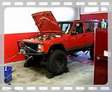
    This will be ongoing so bear with me. This is what I did during the day today. We didn't have a lot of jobs so my boss was like,"why don't you work on your Jeep?" Uh ok!

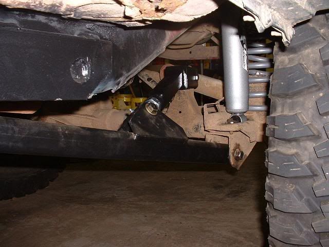
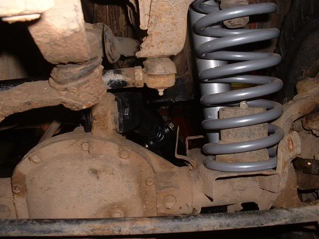
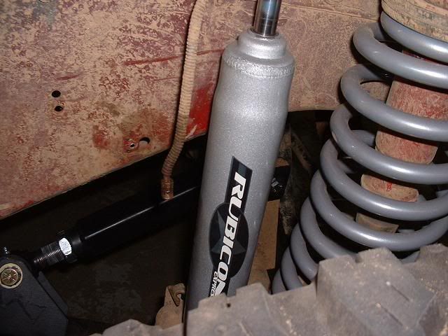
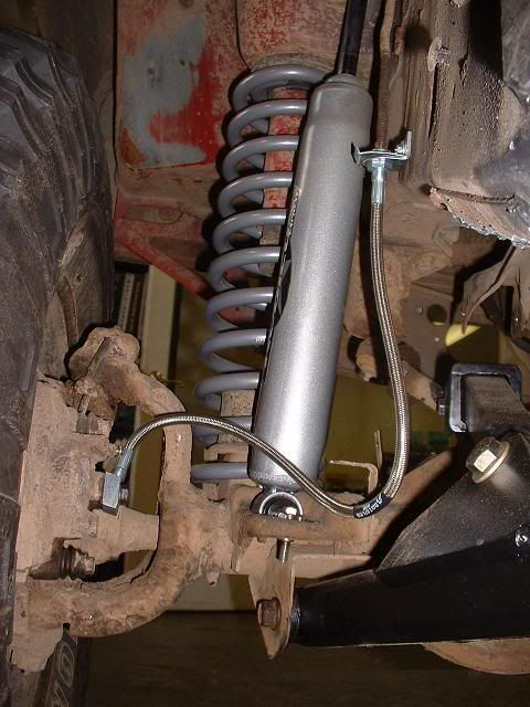
    I have decided that I need some hot long arm action. I will incorporate Unibody stiffeners in my build. I also bought some 4.5" RE coils, 22" brake lines, and 4 RE 4.5-5.5 shocks. That should all be here on the 10th. Im still waiting on parts from extremecrawlers.com.

    Here is how far I got today.
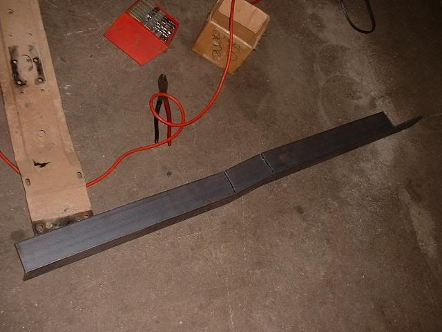
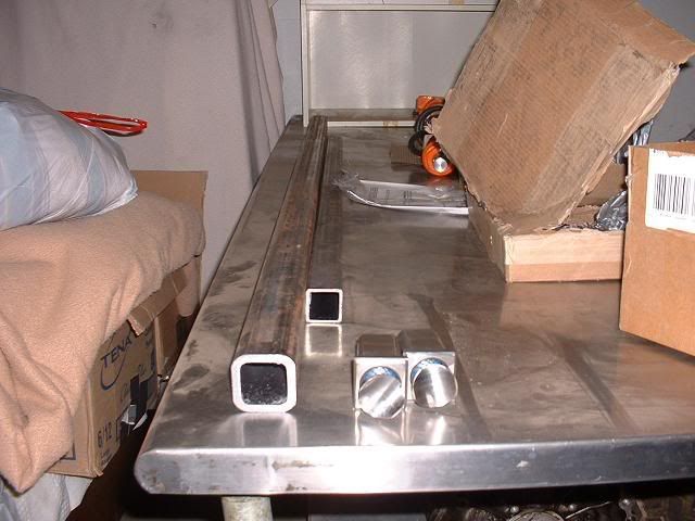
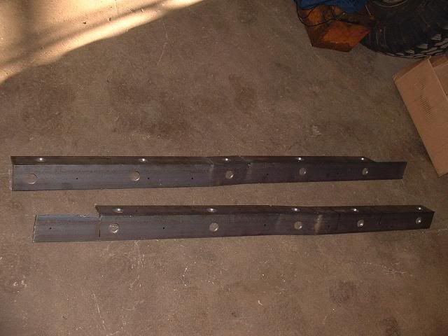
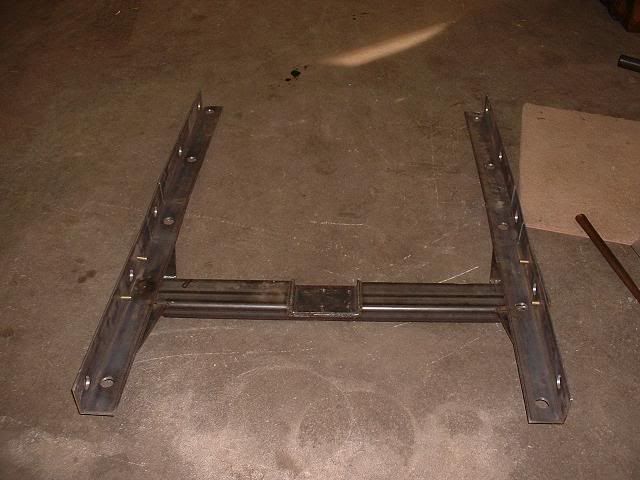
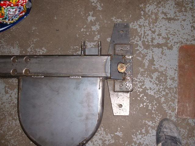
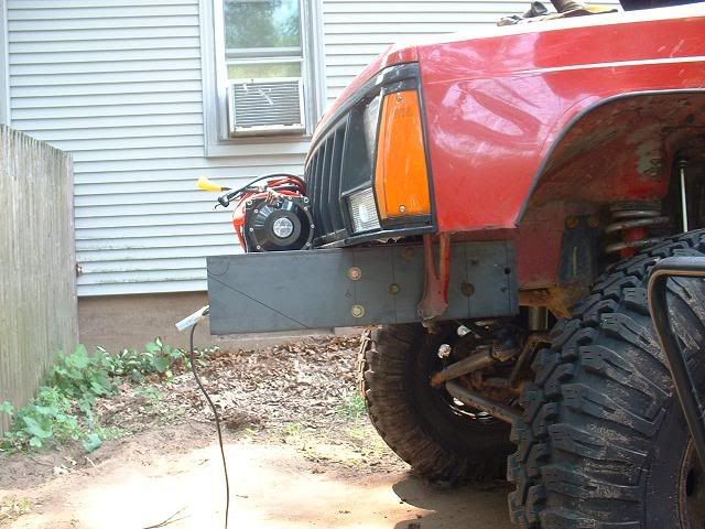
    Here is the unibody stiffener. I am going to weld nuts to the inside on the sides and bottom to bolt the crossmember to. These took all of 15 minutes to make. I did everything free hand with my plasma cutter. I used a press to bend it up. I am going to use a hole saw to make holes to weld through and stitch the edges.


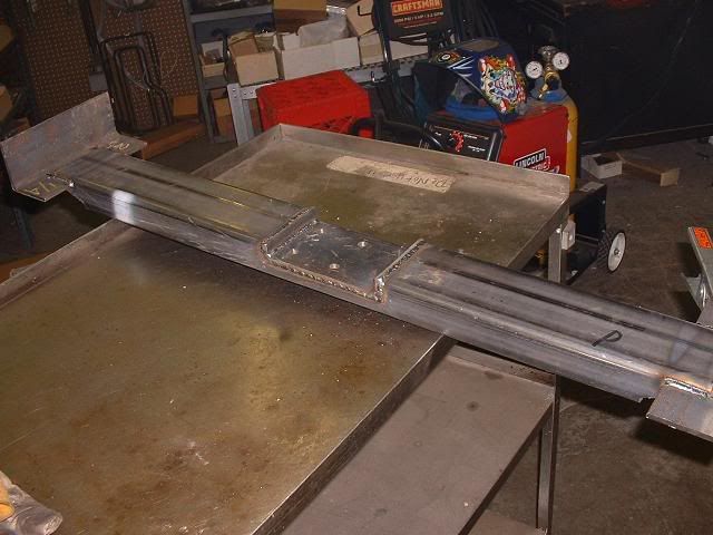
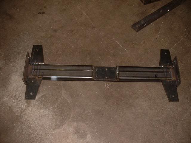
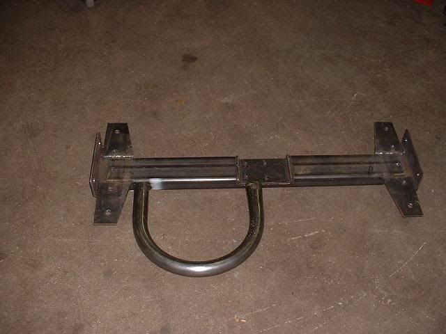
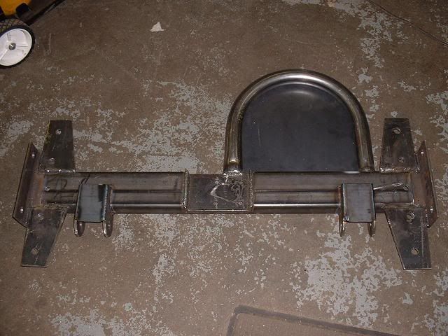
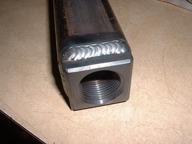
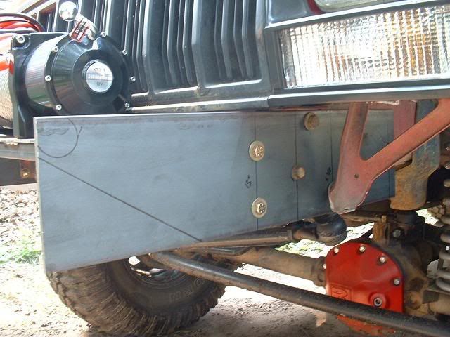
    Next I took out the stock crossmember and started to build the replacement. Keep in mind there is no finish work. I didnt have my grinder and its all free hand plasma work. It will attach with 4 bolts on the bottom and 2 on the sides.


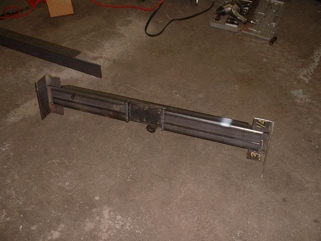
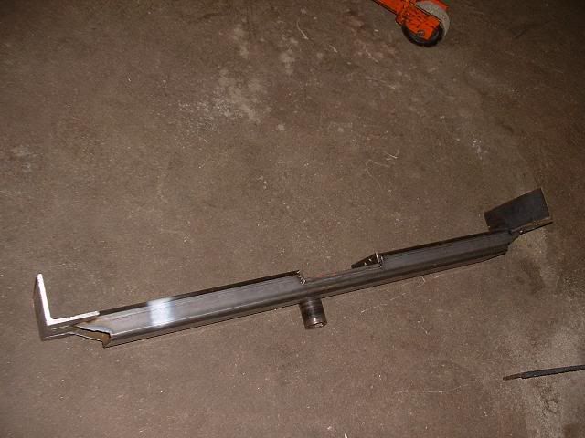
    I still have to make end caps with holes for access and weld it up. Still deciding on TIGing the whole thing or just MIG it...

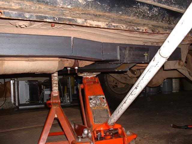
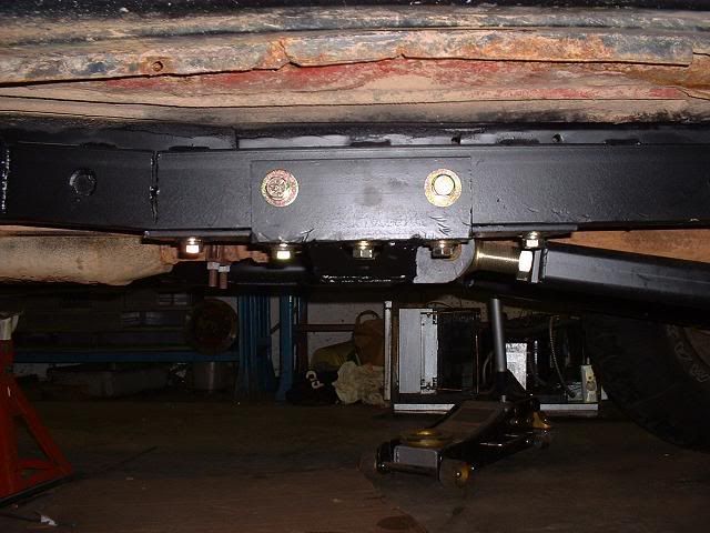
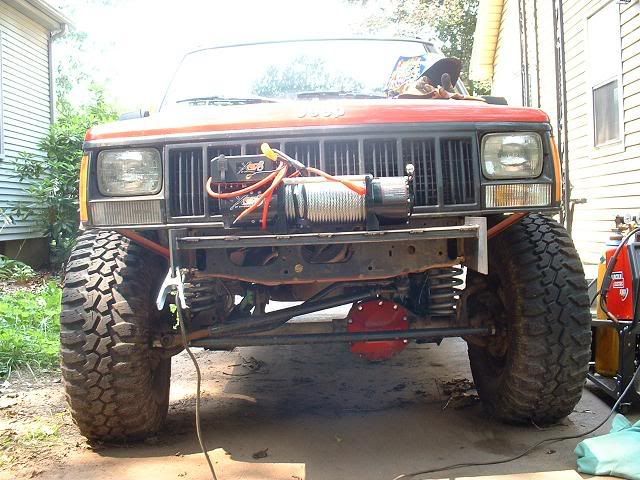
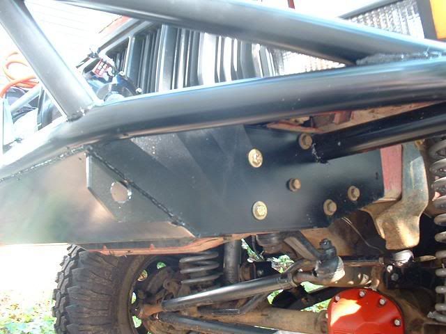
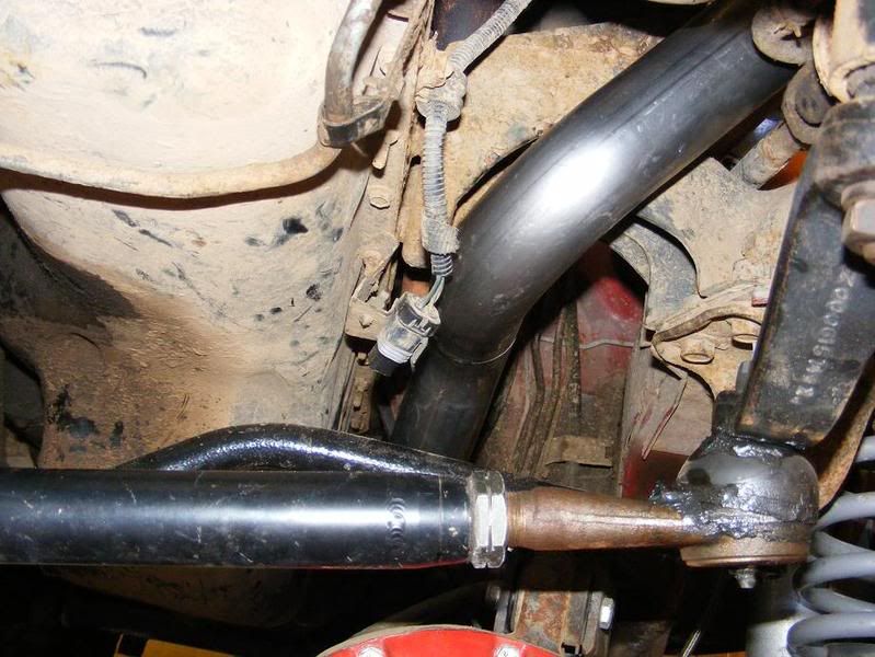
    Here is how it fits. Nice and snug.


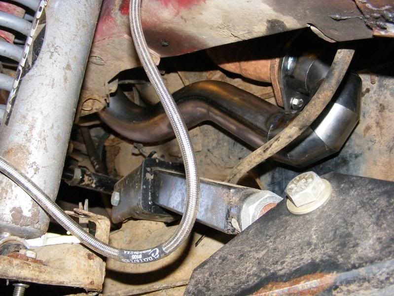
    Next is a pleasant suprise. Well not totally but I didnt think it was that bad.

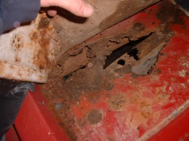
    I have to pull the interior and get it all welded up. Thats gay.

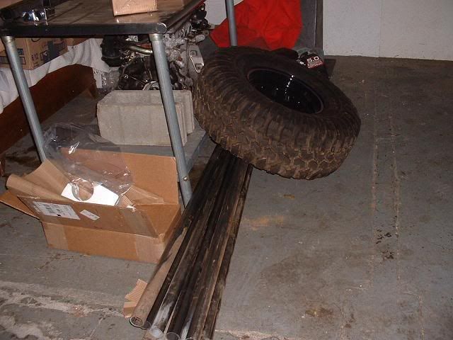
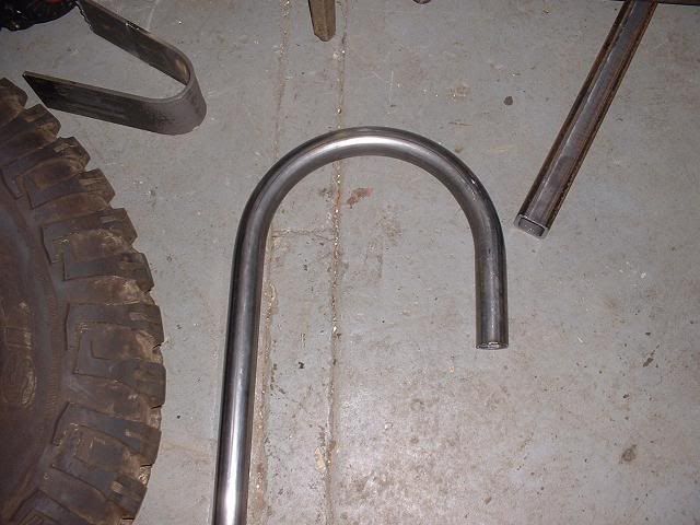
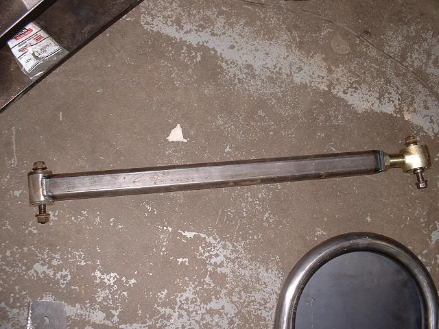
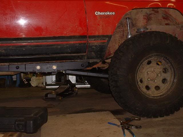
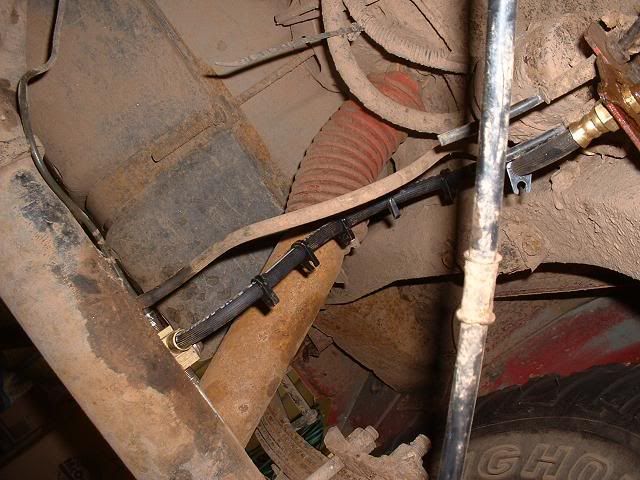
    This is what will be my long arms as soon as my Johnny joints, inserts and bushings get here. 2x.250 square for lowers and some 1.5x1.25 square for uppers.


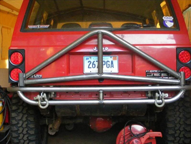
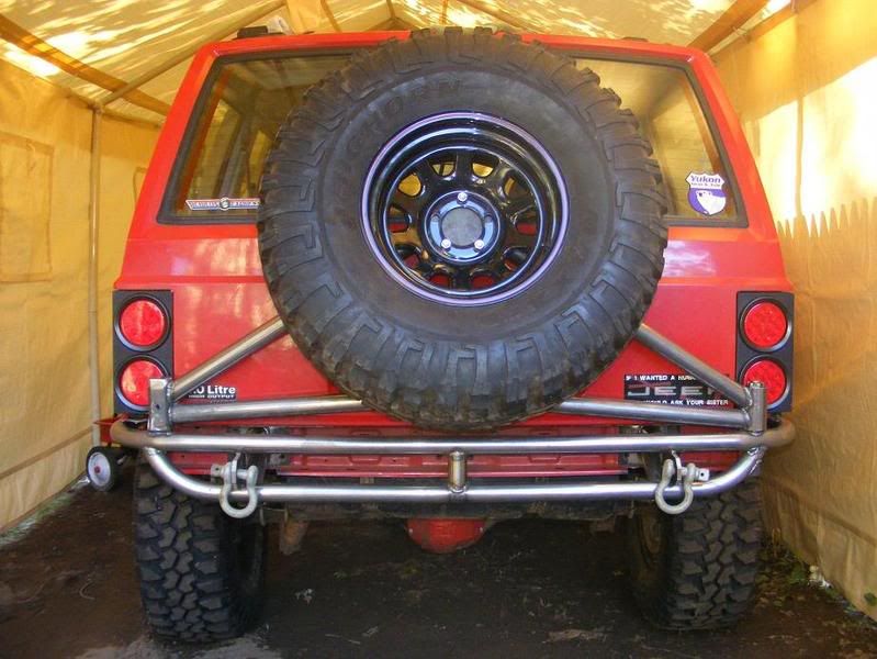
    Here is 100 ft of 1.75x .120 CREW that will end up as my bumpers.


    Employees that helped today.

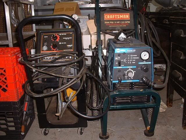
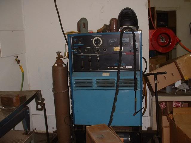
    Here is the old shop whore. Still works like a champ.


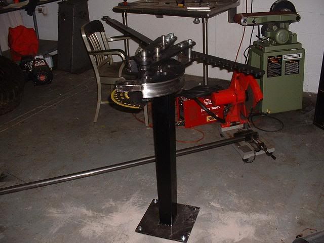
    Ah and my new friend.


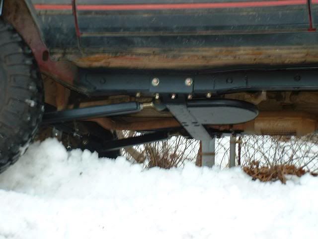
    So plug weld the stiffeners in, make some control arms brackets when my joints come in and then finish the long arms. After that I will be cutting out my rockers and putting 2x6x3/16 in its place.

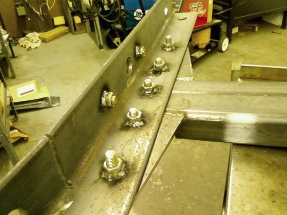
    Had some time today to do a little more. I cut the holes for the unibody stiffeners to weld through. My hole saw has requested a vacation!


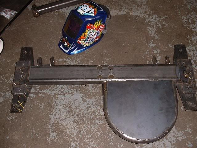
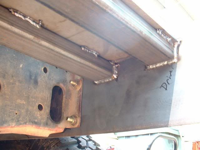
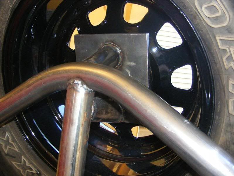
    Here is the crossmember welded up. I always TIG everything but this time I figured I should use the MIG. I never really use it and would like to more. I am seriously considering getting a Miller 212 or 252. I actually enjoyed using the MIG.


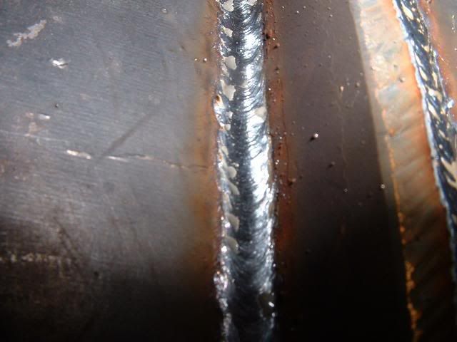
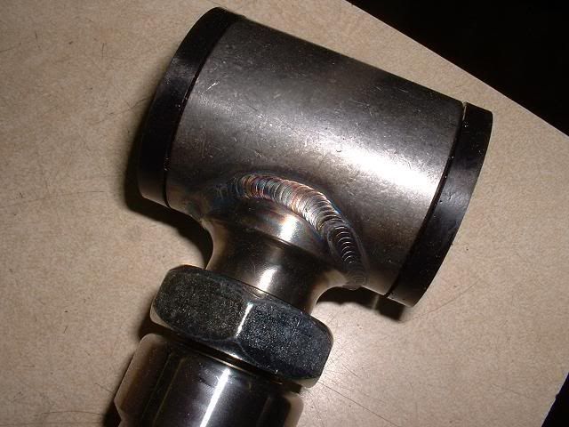
    My camera sucks. (yes, its still the waterfall camera still kicking.) Here is a close up bead. I thought it wasn't bad considering I don't MIG.


    RE stuff should be here tomorrow.....

  • #2
    Crossmember done.


    Here is the mock up. I drilled the 2 side holes on each side through the unibody and now I will finish the drilling on the ground. After that it goes back up for finally drilling and then come back down to hole saw the unibody so I can weld nuts into the stiffeners and it will recess into the "frame"

    Worked on it a bit today. I got it all bolted together and welded in all the nuts to the unibody stiffeners.


    I tried to hole saw the unibody but for some reason the metal grabbed oddly and it ended up breaking the teeth off 3 hole saws. I ended up using the plasma cutter to cut the holes on the unibody to recess the nuts into. Here is the end result. They are partially welded in then I ran out of time.

    sorry for the shitty pics. Its a camera phone. Im lying on the floor.


    Spent most of the day getting the hydraulics on the bender. The first brace I made was cool looking and elborate but in the end wouldn't hold up. In the end I built another one out of the 2x2x.250 that I was going to use for my long arms But now it works awesome.
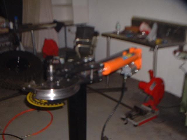
    Here is a blurry ass pic of the bender ready for use.


    Here is the test piece after I got it all working.


    I figured since it bends so nice I should add a transfer case skid to my cross member. I have to skin it later in the week with some 3/16 or 1/4

    Comment


    • #3
      Got some more done this morning. I have the crossmember all finished. All it needs is to be scuffed and painted. Here it is. I TIG'd the long arm brackets on at about 250amps so I know that shit is on there.

      Top

      Bottom


      Here is the bottom arm. I also TIG'd this whole thing. Both ends were heavy multipass affairs. The bushings and sleeves and Johnny Joints were all from extremecrawlers.com. The square inserts were from ballistic.com


      Here is the studs I got from ballistic welded to the sleeves from extreme. They fit perfect out of the box. No gaps. Obviously TIG. These will be welded in the square 1 1/2x1/8 for the top Y link.


      I also finished completely welding in the unibody stiffeners so I need to paint them and the crossmember and install them for the final time. The uppers will need to be measured and assembled. I will then install the new 4.5 springs, shocks and brakelines.
      Been working and not taking pics. Got the long arms all done.

      This is as flat as I could get the belly without using a TNT style plate style crossmember.


      Side


      View from the back

      Front driver side view

      New 4.5 RE springs and 4.5-5.5 shocks.

      22" RE brakelines. Yup they are long enough. I actually my bring the brackets up.

      Here is my new rear line since my old one was a limiting strap. This is from a 96 Dodge Dakota. It was in the $16 range. Its plenty long. You need to file the line end hex off to mount it.

      Testing in the shop parking lot.

      View of the skid.


      Flex? Yeah, check.


      Overall it all works very well. Steering is good and returns as it should. It really needs an alignment but Im going to do some steering on it so fuck that. Im am pleased so far.

      Comment


      • #4
        So I broke out the rear tail light wheeling in Beckett. Once was enough. I figured why bother replacing it with plastic again.

        Here is what I came up with.

        I first found myself trying to measure all the curves of the body. Then I caught myself and realized the entire truck is a beater, why bother. I figured some simple rectangles would do it. I made them out of 1/8th steel. I paid $15 for all the metal and have a bunch left over so I figure $10 for what I used.

        I got the 4" LED's on Ebay for $37.90 shipped. I bought 4 red stop/tails for ease of hook up.

        The LED's were an issue to get hook up correctly. When I hooked up the tail light positive and stop positive with a ground nothing would work but if I unhooked the power for the stop, the tails worked. I figured bleed back was the issue. I had a bunch of diodes left over from chipping Honda ecus. That did the trick.

        Next issue was the dreaded LED fast blink. I solved that by buying an electronic flasher relay that was listed for LED's. I got it at autozone for $13.

        So for $60.90 this is the out come. The wrinkle paint was the only thing I had left but it actually looked ok.


        Comment


        • #5
          Here is the start of my winch bumper. The it will be cut down a bit from here. I will do most of it in tube. The rear will mimick the front. Simple, tube, and light.


          Here it is. I MIG'd the whole thing so no sexy TIG shots.

          Here is how I started. I got the plate hole plots from a PDF on NAXJA that were a bit off. I corrected them before drilling.


          Side plates are .250 and then I used some 1x3 with some .125 on the top to mount the winch.


          Made the tubes on Bend tech pro first and then bent them on the JD2 bender.


          D ring plates are 3/8 and welded on all sides and go 6" deep.


          Wired the ching chong winch this morning and it works. Everything fits nicely. Now I can start on the rear!

          Comment


          • #6
            I started on the laptop with an elaborate tube bumper. I built it on the truck. I mocked and tacked it all up. After I was done I thought it was too much, hung too low and I just didn't like it. It took all day to make. I took the saw to it. My wife thought I was crazy.

            This is what I came up with, with the parts left over. Simple and light. Sorry for the blurry pics. The waterfall camera is ready for the trash. Its all 1.75x.120 HREW. The D ring plates and mount plates are 3/8.


            I already have the tire carrier built on the laptop and printed out. All I have to do it bend it up. I have the A to Z hinge already. I will update it when I have it assembled. It is similar to the C-rok without the flat top.
            Got most the tire carrier done. Need to pick up the plate for the tire mount and the sheet metal to skin it with tomorrow. I am going to add trusses to the carrier and build a latch. Then its just finish work.


            Looky. I got a tire to hang on it. I had to use an engine hoist to lift the wheel into place so I could measure and tack the first tube. What a pain in the ass.


            I think its done except for some finish work. I was going to do some sheet metal and some dimple dies but I think I like it simple.

            Comment


            • #7
              Well I finally got around to mocking some shit up on this piece. I wired in the MSD BTM (boost timing master) and Apexi VAFC ahead of time.

              The BTM basically retards the timing per lbs of boost. This combats detonation.

              The VAFC is a Honda unit by design. It stands for VTEC Air Fuel Controller. This unit does a few things. It can be used to increase or decrease fuel on a load and rpm basis. It will also intecept the MAP signal to the computer and hide boost so the ECU doesn't think there is positive pressure. In its ability to increase or decrease fuel it allows you to use larger injectors and then decrease the duty cycle to inject less fuel back to a stock level.

              Here is the BTM mounted in the truck. It intercepts the coil signal and adapts it.


              Here is where I spliced into the ECU for the air fuel controller. You need to tap onto power, ground, TPS, RPM and splice the MAP wire. You can barely tell its there. All connections are soldered.


              Here are the BTM adjustment knob and the VAFC in the Jeep.


              Here's the turbo mounted to the up pipe. I need to make a stout bracket for it but this just about where its going to live.


              This is the front section of the up pipe. I originally had the pipe to the driver's side but moved it since it didn't look like it would fit my 99 stocker too.


              Here is my short radius bend since chassisshop.com screwed me on my mandrel donut bend. I just radius cut one. This is just tacked together like everything else. It completely clears the control arm mount and driveshaft when compressed.


              Little update. Here is the bracket I made for the turbo. Simple but strong. The angle is 1/4 and is mounted by the 2 bolts that hold the fuel line bracket.


              36 lbs injectors I bought from www.southbayfuelinjectors.com They are bosch style and are one for one direct fit. $140.99 shipped


              Overall shot of the aluminum charge pipe I welded the blow off valve into. Its a simple RFL knock off from ebay. The blow off valve was $24.94 shipped from Ebay. The tubing was left over from another turbo kit. The couplers are from www.siliconeintakes.com they were $44.97 shipped.


              Just need to finish the downpipe, tap the oil pan, run the oil lines and install the gauges. Then its finish work like heat shielding and wrapping the pipes.

              Up pipe and downpipe all welded and wrapped up tight. 2 O2 bungs. One for the stocker and one for my wideband.


              Build totals are shipped to my door.


              Turbo .63/.60 T3/T04E Ebay $185 New
              MSD BTM Shop I work for. $60 New
              Apexi VAFC D-series.org classifieds $85 Used
              PLX SM-AFR/DM5 wideband www.needfultoyz.com $242 New
              AEM air filter Ebay $24 New
              Gauge pod Ebay $14 New
              Boost gauge Ebay $14 New
              Blow off valve Ebay $25 New
              Piping and V-band http://store.racing-solutions.org/ $112.50 New
              Silicone couplers www.siliconeintakes.com $45 New
              36# injectors www.southbayfuelinjectors.com $141 Reman
              Oil lines and fittings local $55 New
              Aluminum charge pipe Left over I had Free New
              T3 flange Weirtech $10 New
              O2 bungs I use jam nuts $5 New
              DEI header wrap Shop I work for. Free New
              Heat shield Homedepot sheet aluminum $10 New
              Misc crap like oil pan gasket, oil, clamps, zip ties, crimp connector, solder, Argon, filler rod. Figure about $ 75

              Total=$1027

              Comment


              • #8
                My mid afternoon project. 2.5 exhaust, stainless flex, magnflow straight through muffler, and some VHT Flame Coat paint.


                Mig welded with whatever I had left over from the turbo piping.

                The magnaflow sounds awesome but with the turbo its super quiet.

                My VAFC will not work properly with my MAP sensor so I need to pull all of that shit out and the injectors and go back to stock injectors and an FMU/pump set up.

                This is gay. Everything else was working mint......

                Comment


                • #9
                  Little update. The AFC and the injectors have been removed. I reinstalled the stocker injectors and I installed an FMU. Which is a rising rate fuel pressure regulator. I also put in a T rex inline pump that was used and proved no good. I ordered and installed a new Walbro GSL392 inline that is working well. I am bleeding off boost to the FMU and its still really rich so its good to know it has enough fuel.

                  The next thing was I had to get rid of the internal wastegate setup. The small internal port would not bleed off enough to regulate boost properly. I removed the swing valve completely and installed a block off plate and a new V band. The only thing left was installing the external wastegate.

                  Since I built the kit with the internal wastegate there is no room for the external anywhere. I finally found a place for it on the up pipe under the intake manifold. I got it all welded up but now the bolts are alomst impossible to get to. I had to remove my track bar to get the pipe back in. I may have to remove the P/S pump and bracket to tighten the wastegate all the way.

                  Other than that its done and it should all work........finally.

                  Comment


                  • #10
                    We made a bunch of pulls with the Jeep today. I was initially upset at the outcome till I did some research.

                    It put down 175hp/226 ft lbs @7-8ish psi at the wheels. I was like WTF!!!!

                    First off with the FMU adding fuel it was ok when the boost comes on but goes 10.5:1 up top which is killing power.

                    Second, we had the scanner on the truck to watch the live stream and it was disturbing. The intake air temp was retarded high. My last pull was in the 195 degree range!!! Ouch. This was the reason the ECM was pulling timing and not making power. We dropped my BTM setting from 1.5 per pound to .25 and it made a bit more power so the intake temps are killing me.

                    On to the power. From the research I did the driveline loss through the auto is around 30%. I found a dyno sheets from a Hesco stroker that JP magazine did. The stroker on the engine dyno make 247/300+ torque. Guess what it dyno'd at in the auto XJ at the wheels? 175/225. lol

                    I am going to crush that number a bit later on. I need to move the IAT from the intake to the charge pipe down stream from the meth injection I am going to add. The meth will allow me to run more timing and keep the ECM from pulling it back out.

                    Second I am going to get rid of the FMU and go back to my 36# injectors. I am going to get a Split Second FTC1 so I can work the injectors and the timing.

                    Here are some pics and one of the pulls.


                    The ass dyno says its making better power. It will get better later in the winter!

                    Here is what we rolled in after my shitbox.

                    2009 Corvette ZR1. What a badass ride. I liked the carbon fiber rotors.

                    Comment


                    • #11
                      Update on the turbo. Pete and I have identified an issue where if in closed loop the ecm will fend off the FMU and create a lean condition under boost. We tried to use a Hobb switch to bypass the TPS and a rheostat to scale the voltage to fool the ECM into open loop. This works on Pete's but not mine since I have automatic. My Jeep wants to downshift. So my next project will be an AW4 tiptronic shifter.

                      Comment


                      • #12
                        Awsome work on the Unibody stiffeners/crossmember .Your build is going great, love the work you've done to your jeep!!!
                        Last edited by imapitbull; 01-28-2009, 05:01 PM. Reason: didn't write what I ment to.

                        Comment


                        • #13
                          this reminds me of how nice of work you do. nuce stuff dave. god i need tools / a garage
                          "when I'm riding my motorcycle,I'm glad to be alive...when I stop riding my motorcycle,I'm glad to be alive"

                          Comment


                          • #14
                            your cross member is beeftastic, great work, wish i could weld anything close to that
                            dirty30

                            Comment


                            • #15
                              thanks. Im going to attempt a first try at the AW4 shifter this week.
                              Last edited by CSaddict; 01-28-2009, 05:05 PM.

                              Comment

                              Working...
                              X